Linear Guide
Linear guides are a special case of elastic joints. They implement a coupling between the source and target interface with linear elasticity and viscous damping properties.
Definition
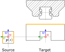
Source and target interfaces should be chosen as shown in following figure:
Source interface
| Type |
Moving interface (Fourier) |
| Topologies |
Side faces of the rail (faces must spread in all directions) |
| Location |
The path should go through the resulting location of action (approx. center of the rail) |
| u direction |
Axial, along the rail in positive moving direction |
| v direction |
Transversal, perpendicular to the rail, sidewards |
| w direction |
Normal, away from the top surface of the rail |
Target interface
| Type |
Stationary interface (6dof) |
| Topologies |
Mounting face of the carriage |
| Location |
Center of action |
| u direction |
Axial, along the rail in positive moving direction |
| v direction |
Transversal, perpendicular to the rail, sidewards |
| w direction |
Normal, away from the top surface of the rail |
Recommended link settings
| Use ground for source |
unchecked |
| Location master |
target |
| Orientation master |
either source or target |
Parameters
Stiffness
| Parameter |
Unit |
Description |
|---|
| Axial (u) |
N/m |
Axial stiffness (usually zero for a linear guide) |
| Transversal (v) |
N/m |
Transversal stiffness |
| Normal (w) |
N/m |
Normal stiffness |
| Roll (ru) |
Nm/rad |
Roll stiffness |
| Pitch (rv) |
Nm/rad |
Pitch stiffness |
| Yaw (rw) |
Nm/rad |
Yaw stiffness |
Damping
| Parameter |
Unit |
Description |
|---|
| Axial (u) |
Ns/m |
Axial damping (viscous damping of the linear guide) |
| Transversal (v) |
Ns/m |
Transversal damping |
| Normal (w) |
Ns/m |
Normal damping |
| Roll (ru) |
Nms/rad |
Roll damping |
| Pitch (rv) |
Nms/rad |
Pitch damping |
| Yaw (rw) |
Nms/rad |
Yaw damping |