Rack and pinion
Rack and pinion link properties implement a rack and pinion drive. Only the linear elastic behaviour is modelled, non-linearities are neglected. The simplifications are:
- any kind of backlash is neglected
- the force pushing the pinion and rack apart (due to the pressure angle of the teeth) is not modelled and has to be added as load in an analysis if desired
- irregular transmission due to the teeth is not modelled
- local deformation of the pinion is not modelled
Definition
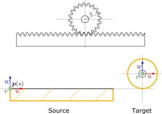
Source and target interfaces should be chosen as shown in following figure:
Source interface
| Type |
Moving interface (Fourier) |
| Topologies |
Side faces of the rack |
| Location |
Along the pitch line |
| u direction |
Axial, along the pitch line |
| v direction |
Transversal |
| w direction |
Normal, towards the pinion |
Target interface
| Type |
Stationary interface (6dof) |
| Topologies |
Peripheral face of the pinion |
| Location |
Center of pinion |
| u direction |
Axial, along the pitch line of the rack |
| v direction |
Parallel to the v-direction of the source interface |
| w direction |
Parallel to the w-direction of the source interface |
Recommended link settings
| Use ground for source |
unchecked |
| Location master |
none |
| Orientation master |
either source or target |
Parameters
| Parameter |
Unit |
Description |
|---|
| Pinion radius |
m |
Radius of the pitch line of the pinion |
| Contact stiffness |
N/m |
Stiffness of the contact between the teeth |
| Contact damping |
Ns/m |
Damping of the contact between the teeth |