Belt drive
Belt drive link properties implement a toothed belt drive. Only the linear elastic behaviour is modelled, non-linearities are neglected. The simplifications are:
the belt is always considered prestressed (both strands are contributing to the stiffness)
the prestress force is not modelled and has to be added as load in an analysis if desired
irregular transmission due to the teeth is not modelled
local deformation of the pulleys is not modelled
Definition
Source and target interfaces should be chosen as shown in following figure:
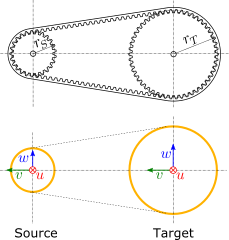
Source interface
Type |
Stationary interface (6dof) |
Topologies |
Peripheral face of the source pulley |
Location |
Center of the source pulley |
u direction |
Axial, along the axis of rotation of the source pulley |
v direction |
Pointing towards the center of the target pulley |
w direction |
Resulting direction |
Target interface
Type |
Stationary interface (6dof) |
Topologies |
Peripheral face of the target pulley |
Location |
Center of the target pulley |
u direction |
Axial, along the axis of rotation of the target pulley |
v direction |
Aligned with the v-direction of the source interface |
w direction |
Parallel to the w-direction of the source interface |
Recommended link settings
Use ground for source |
unchecked |
Location master |
none |
Orientation master |
either source or target |
Parameters
Parameter |
Unit |
Symbol |
Description |
|---|---|---|---|
Source gear radius |
m |
\(r_S\) |
Radius of the pitch line of the source pulley |
Target gear radius |
m |
\(r_T\) |
Radius of the pitch line of the target pulley |
Belt stiffness |
N/m |
\(k\) |
Stiffness of one strand of the belt including tooth compliance |
Belt damping |
Ns/m |
\(d\) |
Damping coefficient of one strand of the belt |
The stiffness of the belt can be calculated using the specific stiffness \(c_{st}\), the width of the belt \(b\), and the free lenght of a strand \(l_{1}\) according to \(k = c_{st} \, b / l_1\).