Gear drive
Gear drive link properties implement a toothed gear drive. Only the linear elastic behaviour is modelled, non-linearities are neglected. The simplifications are:
- any kind of backlash is neglected
- the force pushing the gears apart (due to the pressure angle of the teeth) is not modelled and has to be added as load in an analysis if desired
- irregular transmission due to the teeth is not modelled
- local deformation of the gears is not modelled
Definition
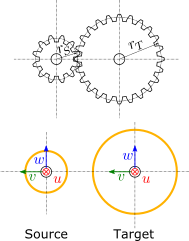
Source and target interfaces should be chosen as shown in following figure:
Source interface
| Type |
Stationary interface (6dof) |
| Topologies |
Peripheral face of the source gear |
| Location |
Center of the source gear |
| u direction |
Axial, along the axis of rotation of the source gear |
| v direction |
Pointing towards the center of the target gear |
| w direction |
Resulting direction |
Target interface
| Type |
Stationary interface (6dof) |
| Topologies |
Peripheral face of the target gear |
| Location |
Center of the target gear |
| u direction |
Axial, along the axis of rotation of the target gear |
| v direction |
Aligned with the v-direction of the source gear |
| w direction |
Parallel to the w-direction of the source gear |
Recommended link settings
| Use ground for source |
unchecked |
| Location master |
none |
| Orientation master |
either source or target |
Parameters
| Parameter |
Unit |
Symbol |
Description |
|---|
| Source gear radius |
m |
\(r_S\) |
Radius of the pitch line of the source gear |
| Target gear radius |
m |
\(r_T\) |
Radius of the pitch line of the target gear |
| Contact stiffness |
N/m |
\(k\) |
Stiffness of the contact between the gears including tooth compliance |
| Contact damping |
Ns/m |
\(d\) |
Damping of the contact between the gears including tooth compliance |