Interfaces#
Bushing interface#
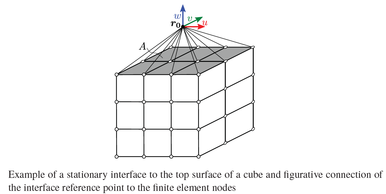
Define interfaces which do not change the position of action on a flexible body. The set of finite element nodes does not change and are thus stationary interfaces.
Name#
Change the name of the interface. Consistent naming of the interfaces simplifies the handling of the links. Physics type shows if the interface is mechanical or thermal. Interface type shows if the interface is abushing or a fourier interface.
Interface topos#
Click on the select button to open the topo-picker. The selected topology is highlighted red.
Type to pick: Choose topology and click on the desired topology. If the topology is hidden click on a node of the topology. This selects all topologies in contact with this node. Click then on undesired topologies to deselect them.
Coordinate System#
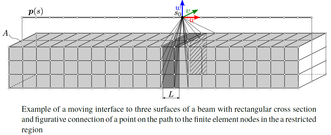
Local coordinate system of the interface. The following color code is used.
Color |
Direction |
Name |
|---|---|---|
Red |
Axial |
u |
Green |
Transversal |
v |
Blue |
Normal |
w |
Select topologies#
Define the origin of the coordinate system. If it should be in the middle of two faces, click on both and it will automatically be in the middle of the selected topologies. The default topology is the topology selected as 6DOF interface.
Offset#
Move the origin of the coordinate system in x-, y- or z-direction of the local coordinate system.
Main/Second axis#
Define the direction of two axes of the local coordinate system compared to the global coordinate. The third axis is then given.
Result#
Show the resulting coordinate system.
Visible#
Show/Hide the coordinate system and scale the arrows of it.
Gauss quadrature order#
Order of the numerical integration to calculate the nodal values at the interface.
Visible#
Show/Hide the interface. In the field a DOF can be selected, which is then shown. The arrow scale can be changed in the arrow scale field.
DOFs for reduction#
A ticked box means that the interface can transmit a force/torque in the given direction according to the table below.
Name |
Definition |
|---|---|
u |
Force in axial direction |
v |
Force in transversal direction |
w |
Force in normal direction |
ru |
Torque around axial direction |
rw |
Torque around transversal direction |
rv |
Torque around normal direction |
Start calculation#
Start the calculation of nodal weights for the specific force distribution. When the calculation is finished, the * in front of the name of the interface disappears. If a * is present, the interface must be updated by running the calculation.
Fourier Interface#
Moving axes of machine tools lead to changing position of coupling elements. The interfaces move depending on the axis position and finite element nodes affected by the interface change. These interfaces are moving interfaces.
Name#
Change the name of the interface here. Consistent naming of the interfaces simplifies the handling of the links.
Interface topos#
Click on the select button to open the topo-picker. The selected topology is highlighted red.
Type to pick: Choose topology and click on the desired topology. If the topology is hidden click on a node of the topology. This selects all topologies in contact with this node. Click then on undesired topologies to deselect them.
Path#
Define the movement path of the carriage. There are two modes to do that task.
Start End Mode#
Start topologies#
Select the start topology. Click choose start topos to open the topo-picker.
End topologies#
Select the end topology. Click choose end topos to open the topo-picker.
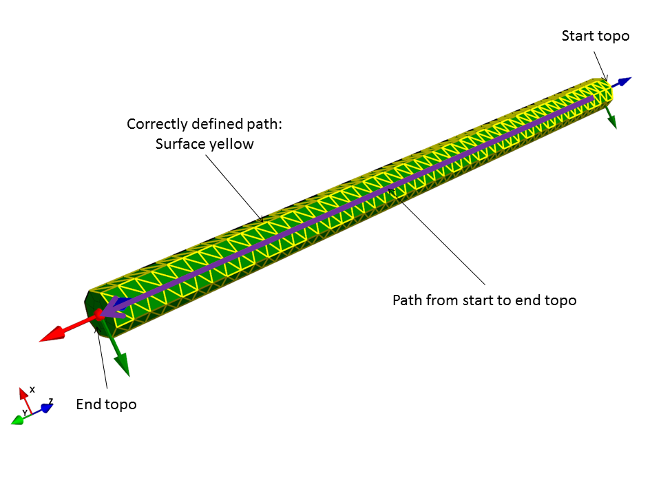
Normal direction#
Define the direction of the normal vector. If the path is not shown like in the picture below, the normal direction of the path has to be changed such that it does not point in the same direction as the path.
Attention#
The definition of the path only works if the topo-picker the type to pick selection is face, edge or node.
Offset#
Move the path in a desired direction.
edges mode#
Edges#
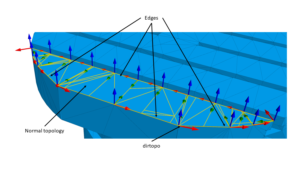
Choose the edges along which the path should run. Click choose edges to open the topo-picker, where the edges can be selected.
Normals#
Define the direction of the normals of the path. Select one of the three modes:
Normals mode |
Normal direction |
|---|---|
elemface_const |
Normal to the selected normal topology face |
elemface_area |
Normal to the selected normal topology face |
in_plane |
In the normal topology face |
Click choose normtopos to open the topo-picker, where the normals topologies can be selected. Reverse the normal direction by selecting the Reversenormal box.
Direction#
Click choose dirtopo to open the topo-picker, where the dirtopo can be selected. Change the direction by selecting the Reversedir box.
Offset#
Move the path in a desired direction.
N harmonics#
The number in this field is defined as follows: N=(length of rail)/(length of carriage)
Normalize#
Option for the normalization of the interface matrix.
DOF type#
Choose between 6dof or 3dof surface.
Maximum distance to path#
Define the maximum distance to the path.
Gauss quadrature order#
Order of the numerical integration to calculate the nodal values at the interface.
Visible#
Select if and how the interface should be shown.
DOFs for reduction#
A ticked box means that the interface can transmit a force/torque in the given direction according to the table below.
Name |
Definition |
|---|---|
u |
Force in axial direction |
v |
Force in transversal direction |
w |
Force in normal direction |
ru |
Torque around axial direction |
rw |
Torque around transversal direction |
rv |
Torque around normal direction |
Start calculation#
Start the calculation of nodal weights for the specific force distribution. When the calculation is finished, the * in front of the name of the interface disappears. If a * is present, the interface must be updated by running the calculation. This may takes some time.